tl;dr
Up till now we've been naively drawing objects potentially on top of each
other. By setting glEnable(GL_DEPTH_TEST), we can only draw pixels if that
part of the object in question is not behind something that has been drawn
before.
GL_ARRAY_BUFFER buffers can contain way more about vertices than just their
location - a trivial example being which colour to draw the vertex as.
Why can I see that line?
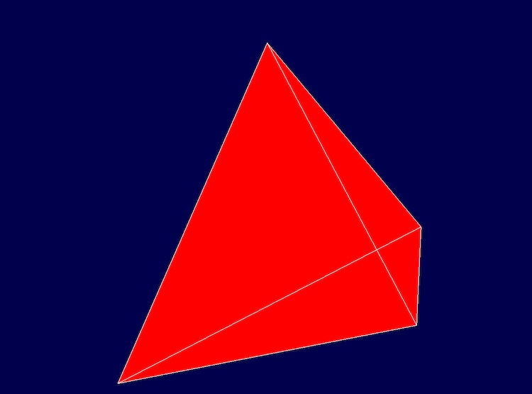
You may have noticed that in the previous demo when borders were added to the tetrahedron, you could see the borders even if they should be "behind" the object.
It's actually quite a bit worse than that, and so first I'll try to demonstrate how much worse.
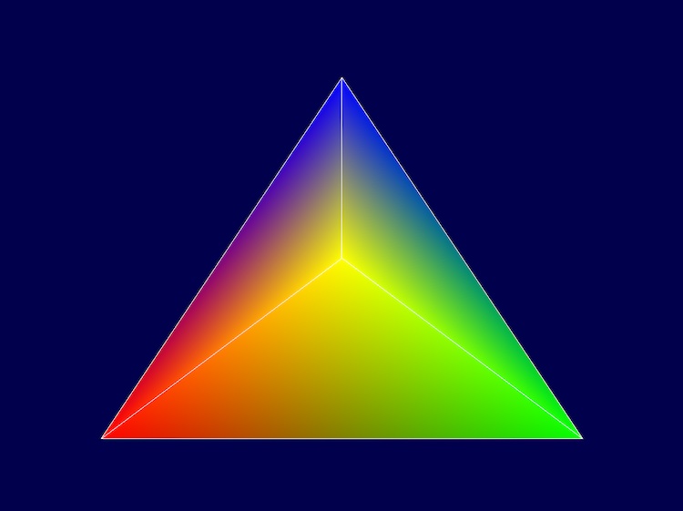
We have been using a single colour for our objects so far, so let's quickly implement different colours.
Vertex attributes
The GL_ARRAY_BUFFER called vertexBuffer currently just contains the
position of the vertex, but we can put any data about the vertex we want in
there. So, let's put the colour we want in there.
Before:
const GLfloat triangleVertices[] = [
    -1f, -1f, 0f, 1f,
     1f, -1f, 0f, 1f,
     0f,  1f, 0f, 1f,
     0f,  0f, 1f, 1f,
];
After:
const GLfloat triangleVertices[] = [
    -1f, -1f,  0f, 1f,   1f,  0f, 0f,
     1f, -1f,  0f, 1f,   0f,  1f, 0f,
     0f,  1f,  0f, 1f,   0f,  0f, 1f,
     0f,  0f, -1f, 1f,   1f,  1f, 0f,
];
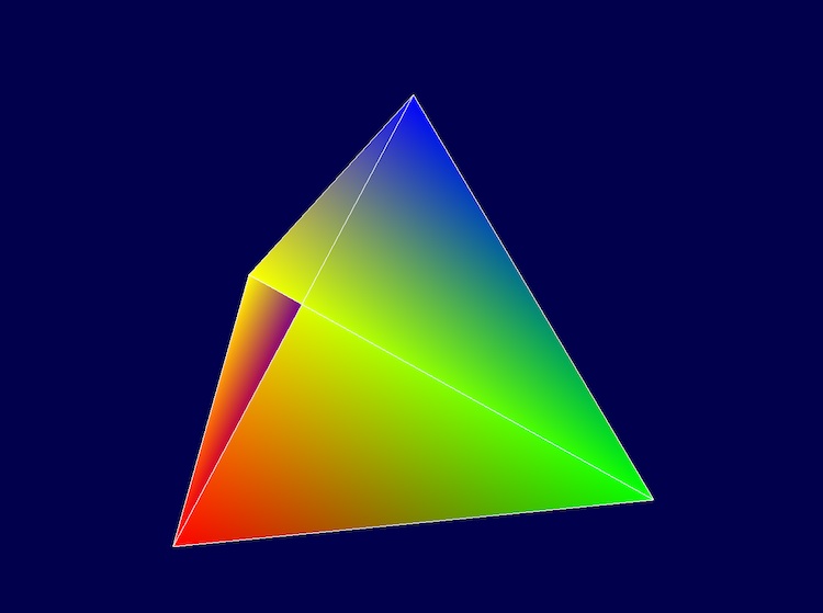
The first vertex is going to be red (rgb of 100%, 0%, 0%), the second green, the third blue, and the final one yellow.
Before we never really explicitly described the layout of the vertex buffer. We simply said to grab 4 values, and left the remainder of the options on their defaults:
 glBindBuffer(GL_ARRAY_BUFFER, vertexBuffer);
glVertexAttribPointer(0, 4, GL_FLOAT, GL_FALSE, 0, null);
glVertexAttribPointer is setting up the first attribute, saying to grab 4
values, of type float. The GL_FALSE here means that the values are already
normalized to between -1f and 1f, and so they don't need to be.
The 0 describes the length of each vertex (known as the "stride") - in this
case we're using 0 and not a specific length to mean that the vertex is as
tightly packed as could be - ie, its length is 4 floats.
The null at the end says that the 4 values we want are the first four values
- we don't need to skip any values. If we did need to, we would need to give
the offset.
Although this could be done differently, I'm going to create two VertexAttribPointer to show how to use "stride" and "offset". We'll be introducing the second attribute to pass to the shader that represents the colour. It will be three values (one each for red, green, and blue), and we would need to skip the first four values (which contain the position).
First, let's see what introducing these new values for each vertex does to our first attribute:
glBindBuffer(GL_ARRAY_BUFFER, vertexBuffer);
glVertexAttribPointer(0, 4, GL_FLOAT, GL_FALSE, 7 * GLfloat.sizeof, cast(void*)(0 * GLfloat.sizeof));
Now we need to tell glVertexAttribPointer that the "stride" of each vertex is
7 float values (we need to give the number of bytes, not the number of values,
hence the multiplication by the size of the float).
I've also expanded the null from before into what it actually represents - an
offset of 0 float values.
Now with the second attribute:
glBindBuffer(GL_ARRAY_BUFFER, vertexBuffer);
glVertexAttribPointer(0, 4, GL_FLOAT, GL_FALSE, 7 * GLfloat.sizeof, cast(void*)(0 * GLfloat.sizeof));
glVertexAttribPointer(1, 3, GL_FLOAT, GL_FALSE, 7 * GLfloat.sizeof, cast(void*)(4 * GLfloat.sizeof));
Now, it is a bit clearer that we are grabbing 3 float values, that are offset from the beginning of the vertex by 4 float values.
Now we need to adjust the shaders to handle this. Our fragment shader already has the colour being passed in from the vertex shader, so it actually doesn't need to change. The vertex shader now looks like this:
#version 330 core
layout(location = 0) in vec4 pos;
layout(location = 1) in vec3 color;

uniform mat4 u_transform;
uniform int is_line;

out vec3 Color;

void main(){
    if (is_line == 0) {
        Color = color;
    } else {
        Color = vec3(1, 1, 1);
    }
    gl_Position = pos * u_transform;
}
There are only two lines differing - the layout(location = 1) in vec3 color
line introduces the second attribute, and the Color = color line replaces the
old hardcoding line that was Color = vec3(1, 0, 0) before.
This looks kinda interesting when rendered before the rotation kicks in:
Here is the state of the code repo at this point.
Depth
Unfortunately, when we actually rotate the object, we quickly see that we're not getting each face drawn properly - instead some faces that should be "behind" are being drawn over the faces that are actually in "front", much like the lines from the last demo.
The depth buffer can help us avoid this. It associates a depth value with every pixel location, and will only replace the pixel at a location if the new value to be written there is something that appears in "front" of the last thing that was written there.
It is pretty easy to use, with a minor caveat - if you forget to set
glClearDepth at the start, you may just not see anything drawn ever, as the
renderer will think no pixels are any closer than the default.
The setup is (place it somewhere near where you're calling glClearColor to
set the default background color):
glClearColor(0.0f, 0.0f, 0.3f, 0.0f);
glClearDepth(1f);
glEnable(GL_DEPTH_TEST);
glDepthFunc(GL_LESS);
In your display loop, where you clear the screen back to the default colour
with glClear, just add the GL_DEPTH_BUFFER_BIT to the clear, like so:
glClear(GL_COLOR_BUFFER_BIT|GL_DEPTH_BUFFER_BIT);
The end result:

Putting it together
Here is the state of my code repo at this point.
Here is a short demo of what it looks like at this point: